I’ve used graphics libraries such as OpenGL in the past, but what was going on under the hood felt like magic to me. In order to investigate how it works I developed my own software renderer, tinysr, in rust. The following is an overview of how the library works. Big thanks to Dmitry Sokolov’s written up guide at https://github.com/ssloy/tinyrenderer/wiki.
Shader Pipeline Link to heading
OpenGL, which tinysr mimics, describes the following rendering pipeline:
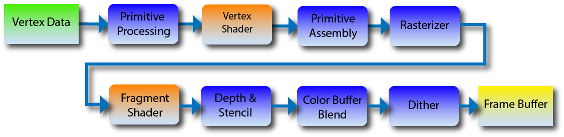
We’ll be skipping over some steps, but we are interested in the vertex shader and fragment shader steps. For each vertex we draw, we transform the vertex first by calling the pipeline’s vertex shader. Then in the rasterization step, we execute the fragment shader to get the specific pixel color. For now our pipeline can be represented by the following:
struct Pipeline;
impl Program for Pipeline {
    type Vertex = [f32;3];

    fn vertex(&self, v: &Self::Vertex, position: &mut [f32;4]) {
        *position = [v[0], v[1], v[2], 1.0];
    }

    fn fragment(&self, color: &mut [f32;4]) -> Fragment {
        *color = [1.0, 1.0, 1.0, 1.0];
        Fragment::Keep
    }
}
tinysr is designed to have no dependencies, thus need to know what format vertex data is being provided. This is represented via the type Vertex in the Program trait.
Note that, like OpenGL, the vertex shader uses homogenous coordinates. This is common in computer graphics to allow us to perform various transformations using 4-by-4 matrices. This will be important if we want our users to use projection transformations. To convert our 4d vector into $\mathbb{R}^3$, we scale the first three coordinates by the forth. In other words, $(x,y,z,w)\rightarrow(x/w,y/w,z/w)$.
With this pipeline, the goal is create a set of vertex data and run the pipeline.
let mut tinysr = TinySR::default();
tinysr.set_viewport(0,0, WIDTH,HEIGHT);

let shader = Shader;
let vertices = vec![
    //  X     Y    Z
    [-0.5, -0.5, 0.0],
    [ 0.5, -0.5, 0.0],
    [ 0.0,  0.5, 0.0],
];
tinysr.draw_array::<Points,_>(&shader, &vertices);
For the vertices’ position data we use normalized device-coordinates (NDC) for position data. Using NDC simplifies rendering for the user. For our image we have a pixel grid $(0,0)\times(w,h)$ but don’t want our end-user to have to worry about transforming data to their desired viewport. Thus the user provides data in NDC where items on the screen lie in $(-1,-1)\times(1,1)$. Sometimes the space using NDC is called clip-space as opposed to screen-space. Before we draw to the screen we can simply convert between spaces.
pub fn conv_ndc_coords(&self, x: f32, y: f32) -> [i32;2] {
    let x = (self.viewport.size[0] as f32 / 2.0) * (x + 1.0) + self.viewport.origin[0] as f32;
    let y = (self.viewport.size[1] as f32 / 2.0) * (y + 1.0) + self.viewport.origin[1] as f32;
    [x as i32, y as i32]
}
With our vertex data in NDC we can use the draw_array method which takes in the shader pipeline and vertex data and passes the data into the rasterization algorithm handled by a Primitive trait, in this case Points which simply draws a pixel at each vertex.
pub struct Points;
impl Primitive for Points {
    fn draw<P: Program>(program: &P, vertices: &[&P::Vertex], target: &mut ScreenBuffer) {
        for vertex in vertices {
            let mut trans_v = [0.0;4];
            program.vertex(vertex, &mut trans_v);
            let mut color = [0.0;4];
            let discard = program.fragment(vert_out, &mut color);
            if discard == Fragment::Keep {
                target.draw_ndc(trans_v[0]/trans_v[3], trans_v[1]/trans_v[3], color);
            }
        }
    }
}
Resulting in the following:

Drawing Triangles Link to heading
With the framework setup, it is time to actually draw something interesting. Luckily, drawing triangles turns out to be quite simple. We can simply iterate through each pixel, if the pixel is inside the triangle then we draw the pixel. To optimize this, we can only check pixels within a bounding box of the triangle.
Consider the following algorithm taking in 3 points in screen coordiantes:
let bbox = create_bounding_box(a,b,c); // a,b,c are the three vertices in screen space.
for x in bbox.min[0]..=bbox.max[0] {
    for y in bbox.min[1]..=bbox.max[1] {
        if is_point_in_triangle(a, b, c, [x,y]) {
            // draw pixel at (x,y).
        }
    }
}
Now the obvious question is how do we know if our point is inside the triangle? We can make use of barycentric coordinates. The Wikipedia article for barycentric coordinates is very abstract and unhelpful for us. For our application, barycentric coordinates provide a way to represent a point as a weighted sum of the triangle’s vertices. For a triangle $ABC$ and point $P$, we want weights $\alpha,\beta,\gamma$ such that $P=\alpha A + \beta B + \gamma C$ and $\alpha+\beta+\gamma=1$. With this, as long as all three weights are non-negative the point lies within the triangle.
fn is_point_in_triangle(a: [i32;2], b: [i32;2], c: [i32;2], p: [i32;2]) -> bool {
    // calculate barycentric coords.
    let u1 = [c[0]-a[0], b[0]-a[0], a[0]-p[0]];
    let u2 = [c[1]-a[1], b[1]-a[1], a[1]-p[1]];
    let u = cross_product(u1, u2);

    let bc = if u[2].abs() < 1.0 {
        return [-1.0,1.0,1.0];  // Triangle is degenerate.
    } else {
        [1.0 - (u[0]+u[1])/u[2], u[1]/u[2], u[0]/u[2]]
    }

    return bc[0] >= 0 && bc[1] >= 0 && bc[2] >= 0;
}
I’ll skip over the math behind this function. If you are interested, you can assume $\gamma=(1-\alpha-\beta)$ leaving you with a two equations and two unknowns. The algebra becomes messy quite quickly.
With this, we can finally draw our triangle.
fn draw<P: Program>(program: &P, vertices: &[&P::Vertex], target: &mut ScreenBuffer) {
    let ntris = vertices.len() / 3;
    for i in 0..ntris {
        let mut pts = Vec::new();
        for j in 0..3 {
            let mut pt = [0.0;4];
            program.vertex(&vertices[i * 3 + j], &mut pt);
            pts.push([pt[0]/pt[3], pt[1]/pt[3], pt[2]/pt[3]]);
        }

        // convert the points to screen space and draw the triangle
    }
}
Resulting in the following:

Extending our Pipeline Link to heading
Right now the vertex shader and fragment shader can’t communicate. If we want our fragment shader to do more than return a solid color, we need to find a way to bridge the two.
impl Program for Shader {
    type Vertex = [f32;6];
    type VertexOut = [f32;3];

    fn vertex(&self, v: &Self::Vertex, position: &mut [f32;4]) -> Self::VertexOut {
        *position = [v[0], v[1], v[2], 1.0];
        [v[3],v[4],v[5]]
    }

    fn fragment(&self, v: Self::VertexOut, color: &mut [f32;4]) -> Fragment {
        *color = [v[0], v[1], v[2], 1.0];
        Fragment::Keep
    }
}
Now our vertex data includes vertex color.
let vertices = vec![
    //  X     Y    Z      R    G    B
    [-0.5, -0.5, 0.0,   1.0, 0.0, 0.0],
    [ 0.5, -0.5, 0.0,   0.0, 1.0, 0.0],
    [ 0.0,  0.5, 0.0,   0.0, 0.0, 1.0],
];
In order to get our new pipeline working, there’s one slight problem to tackle first. The pipeline runs the vertex shader once per vertex, but the fragment shader once per pixel. What vertex data is passed to what fragment?
The answer is all of them! More specifically, we linearly interpolate the values of VertexOut between all vertices for each pixel. To get this working in rust I added an Interpolate trait which takes in $N$ values and $N$ weights and returns a new value. We then require the type VertexOut in our pipeline to implement the Interploate trait.
Now when we run the vertex shader we store the output along with the position data and use them when we run the fragment shader. Below is the triangle primitive taking advantage of this using our barycentric coordinates as weights.
let data_interp = P::VertexOut::interpolate(
    &[a_data.clone(), b_data.clone(), c_data.clone()],
    &bc
);
let mut color = [0.0;4];
if program.fragment(data_interp, &mut color) == Fragment::Keep {
    target.draw(x, y, color);
}
Now our triangle is fully colored!

Adding Depth Link to heading
Right now our renderer has a race-condition problem. If a triangle in the back is drawn after one in the front, the wrong triangle will be drawn. We see this in action when trying to draw a more complex model such as a teapot:

We can correct this with a z-buffer. A z-buffer is a simple concept. When we draw a pixel to the screen, we record it’s z-value, i.e., it’s depth. If the current pixel’s z-value is greater than what we are trying to render than we stop drawing that pixel. We just have to remember to reset each pixel of the z-buffer to $-\infty$ before we start drawing.
This requires a slight alteration to our triangle drawing. We now need to pass in a z-value and use our barycentric coordinates to calculate the z-value of each pixel.
let mut z = a[2] * bc[0] + b[2] * bc[1] + c[2] * bc[2];

if target.write_zbuffer(x, y, z) {
    // draw the pixel
}
The method write_zbuffer above attempts to write to the z-buffer. If a greater z-value is present, the method stops and returns false. Otherwise it updates the z-buffer and returns true.
With this simple adjustment our teapot is now rendering correctly!

The full code can be seen on GitHub at: https://github.com/AmberThrall/tinysr/